Tech Page
Picking
a gear ratio - Changing
valve springs - Building
a Honda race engine - Handy
downloadsFinding your optimum gear ratio.
Finding the optimum gear ratio that suits your engine, driving style and track
conditions can make the difference in qualifying and your race results.
When
considering gear ratios I think of the overall ratio, by this I mean the number
of revs of the engine required to move the kart 1 meter. This takes into account
three factors, driver sprocket teeth, driven sprocket teeth, and roll out, or
circumference, of the tires. When you change tires or even inflation pressure
and the roll out changes you can compensate for this by adjusting the sprockets
to obtain the same overall ratio. The formula for overall ratio is:
OR(r/m)
= 39.37 x Driven teeth / Driver teeth / Roll out (inches)
Example, for a 10 tooth driver, 88 tooth driven and a 34.5
in. roll out OR = 39.37 x 88 / 10 / 34.5 =10.04 rev/meter
Note that the
higher the ratio is its numerical value is lower and vice versa.
When trying a different gear ratio you want to evaluate
its result on your performance. The stopwatch may tell the story, but you also
probably want to know how your top speed was affected. If you use a tachometer
with a maximum recall you can use this to calculate your top speed. The formula
for speed is:
V (km/h) = RPM x Driver teeth x Roll out / Driven teeth /
656.2
So for the above example at 15000 rpm the speed is V =
15000 x 10 x 34.5 / 88 / 656.2 = 89.6 km/h.
As a general rule I believe its best to find the lowest
ratio that does not cause a loss of top speed or over revving of your engine, as
this will give the best jump out of the slow corners. Don't ignore the stopwatch
either. For quick reference I like to use a chart that shows the overall ratio
and maximum speed for the typical ratios you would use and your typical maximum
RPM. This can be done manually or on a spreadsheet program. I limit my charts to
the gears I have in my toolbox and sort it by overall ratio. Here is a sample
you can expand on.
| Overall Gear Ratio
Chart |
Speeds shown are km/h
at - |
6400 |
RPM |
|
| Roll
out-> |
33.75 |
34.00 |
34.25 |
34.50 |
34.75 |
| Driver |
Driven |
OR |
Speed |
OR |
Speed |
OR |
Speed |
OR |
Speed |
OR |
Speed |
| 13 |
64 |
5.74 |
66.87 |
5.70 |
67.36 |
5.66 |
67.86 |
5.62 |
68.35 |
5.58 |
68.85 |
| 13 |
62 |
5.56 |
69.02 |
5.52 |
69.53 |
5.48 |
70.05 |
5.44 |
70.56 |
5.40 |
71.07 |
| 13 |
60 |
5.38 |
71.32 |
5.34 |
71.85 |
5.31 |
72.38 |
5.27 |
72.91 |
5.23 |
73.44 |
| 14 |
64 |
5.33 |
72.01 |
5.29 |
72.54 |
5.25 |
73.08 |
5.22 |
73.61 |
5.18 |
74.14 |
| 13 |
58 |
5.20 |
73.78 |
5.17 |
74.33 |
5.13 |
74.88 |
5.09 |
75.42 |
5.05 |
75.97 |
| 14 |
62 |
5.17 |
74.33 |
5.13 |
74.88 |
5.09 |
75.43 |
5.05 |
75.98 |
5.02 |
76.53 |
| 13 |
56 |
5.03 |
76.42 |
4.99 |
76.98 |
4.95 |
77.55 |
4.92 |
78.12 |
4.88 |
78.68 |
| 14 |
60 |
5.00 |
76.81 |
4.96 |
77.38 |
4.93 |
77.95 |
4.89 |
78.52 |
4.86 |
79.09 |
| 15 |
64 |
4.98 |
77.15 |
4.94 |
77.72 |
4.90 |
78.30 |
4.87 |
78.87 |
4.83 |
79.44 |
| 14 |
58 |
4.83 |
79.46 |
4.80 |
80.05 |
4.76 |
80.64 |
4.73 |
81.22 |
4.69 |
81.81 |
| 15 |
62 |
4.82 |
79.64 |
4.79 |
80.23 |
4.75 |
80.82 |
4.72 |
81.41 |
4.68 |
82.00 |
| 14 |
56 |
4.67 |
82.30 |
4.63 |
82.91 |
4.60 |
83.52 |
4.56 |
84.12 |
4.53 |
84.73 |
| 15 |
60 |
4.67 |
82.30 |
4.63 |
82.91 |
4.60 |
83.52 |
4.56 |
84.12 |
4.53 |
84.73 |
| 15 |
58 |
4.51 |
85.13 |
4.48 |
85.76 |
4.44 |
86.40 |
4.41 |
87.03 |
4.38 |
87.66 |
| 15 |
56 |
4.36 |
88.17 |
4.32 |
88.83 |
4.29 |
89.48 |
4.26 |
90.13 |
4.23 |
90.79 |
|
|
|
|
|
|
|
|
|
|
|
|
Click here
to download the XL spreadsheet that you can customize.
top of
page
Changing valve springs at
the track
Or anywhere else for that
matter. Although I have never seen a valve spring break, they do start to take a
permanent set (collapse) pretty quick. So we put fresh springs in every 2 or 3
races. The springs are pretty cheap (about $3 each) and easy to change without
removing the head. So it is good insurance to change them often.
Here's the way I do it. Remove the valve cover and spark
plug, then turn the engine over until the piston is at top dead center on the
compression stroke (Both valves are closed). I use a screwdriver in the spark
plug hole to feel the piston at top position. With a screwdriver in one hand,
push the valve spring keeper down enough to turn the rocker arm to one side of
the valve with the other hand, thus exposing the spring keeper. Remove the valve
rotator "pill" from the exhaust valve stem. Unpack the new springs and have them
sitting upright within reach, ready to use. Fish the bent end of an "L" shaped
Allen Key into the spark plug hole and position it so that it holds the valve
closed by levering it against the piston top with light force (don't force
piston down). While holding the valve shut with the Allen Key in one hand use
the other hand to remove the valve spring keeper and spring, install the new
spring and re-engage the spring keeper. Replace the exhaust valve "pill". Press
the spring keepers down as before and engage the rocker arms. Check and adjust
the valve lash. It should not have changed, as we did not touch the adjuster
nuts. This process only takes 5 minutes, but don't rush it, and don't be
interrupted while you are doing it. You don't want to drop the valve into the
cylinder. Note that the two spring keepers are different, as only one accepts
the exhaust rotator pill, so don't mix them up. If you accidentally drop a
valve, it may still be engaged in the valve guide. You can usually fish it back
up with the Allen Key or by carefully raising the piston if it has gone down a
bit. Otherwise you have to remove the head to recover the valve (very rare).
top
of page
Race prep your Honda
engine
To get a race prepared Honda you've got a few options. You
can buy a new race ready engine form one of the several engine builders in your
area (in the Vancouver area I suggest Red Head or Bulldog. You can buy a used
motor from another racer. If you buy a used motor, you should go through it or
have it freshened up before it is run. Or you can buy a new Honda and do the
race prep yourself. This is the route we took. It saved us some money, but the
greatest reward is when you beat some of the pro-built engines. I'll go through
what you should do to get going with a Honda GX200 (6.5 hp) or GX160K1 (5.5 hp)
engine.
Start with a copy of the ASN Canada rule book and
a repair manual that covers these engines (Haynes Small Engine Repair is fine).
The modifications that we will make to the engine are as follows.
First the engine is
disassembled. Just a couple of points here. Secure the engine to your work
bench. I leave the motor mount on and clamp it in the bench vice. Remove the
flywheel before removing the the crankcase side cover. To remove the flywheel,
remove the nut by locking the flywheel with a large screwdriver inserted through
a slot in the top of the case. Remove the starter cup and fan and put the nut
back on loosely to catch the flywheel when it breaks loose. I then use 2 large
screw drivers to apply pry pressure to the flywheel, while at the same time
giving the face of the flywheel a sharp blow beside the crankshaft nut. Before
removing the cam, make sure you can see the timing gear alignment marks. The one
on the crank gear is usually very light. You do not have to remove the rocker
arm adjusters, just disengage the rockers by pushing the valve spring retainer
down and turning the rocker sideways. Note that the valve spring retainers are
different, the exhaust has a special retainer and button that allows valve
rotation during operation. And there is a valve stem seal on the intake only (on
newer engines only). Toss the stock valve springs, we will be using G200 (not
GX200) springs for racing.
Remove the
governor components. With the crank removed, remove the thin governor drive
gear (not the timing gear) using a hammer. Remove the governor lever pivot
shaft, leaving a hole in the top of the case. Remove the governor by prying out
the small wire circlip with a small screwdriver. This little clip is difficult
to get out. I finally took an old screwdriver and ground a little notch in the
end so I could hook it. The governor shaft is left in place. The lever pivot
hole must be plugged. The hole will accept a 5/16 NC tap as is. Thread the hole
to accept a 5/16 set screw, and stop the threads before you get to the bottom of
the hole so that the set screw will stop before falling into the case. Use some
sealant like Permatex on the set screw. I have the set screw down deep enough
(3/4") so that I can put a 5/16 bolt in over top of it. I use this bolt as the
pivot for my home made throttle relay lever. On my first engine I tried using
the stock governor lever and pivot shaft for my throttle relay, but it was a bad
idea. The pivot shaft hole wore quickly and allowed oil to weep out and dirt to
get into the engine.
Just a note about removing surplus
junk from your engine. Most people remove the decompression mechanism from the
camshaft. I don't do this anymore, and I recomend leaving it functional. Without
the decompressor and with advancd ignition timing these engines have a tendency
to backfire when you are starting them. When this happens it reaks hovock with
the recoil starter pawls, which need more frequent replacement and can cause you
to miss a heat if you can't start in time. In two years with the decompressor
working I have yet to replace a starter pawl. The only thing is that the engine
tends to need the choke partially on to fire with the lower compression, even
when hot. The decompressor releases below idle speed so it does not impede
performance at all.
Re fit the
piston ring gap. The stock ring gap is quite large and allows compression
leak down. We want to reduce this gap to a minimum and thus keep as much
compression pressure as possible. To do this we start with a new ring set for a
bore size one step larger than the actual bore. You are allowed to use Honda
oversize pistons of which there are three sizes, 0.25 mm, 0.50 mm, and 0.75mm
oversize. Although the larger bore will produce more power, my experience is
that the difference is barely noticeable. Just because the overbore is better I
have my engines bored for the 0.50 mm piston from the start. This allows me to
use 0.75 mm over rings and custom gap them. I don't recommend boring 0.75 mm
over as there are no bigger rings available and you will probably lose more with
the big gap than you gained from the bore increase. The difference in
performance due to over boring is so small that a stock bore engine will still
be competitive. It's your choice here.
Anyway, on to
fitting your rings. We are going for a 0.006 inch gap. Before grinding, the
rings will not fit in the cylinder as the ends will overlap. I grind one end
only of the ring with a hand held stone. In order to avoid damage to the other
end of the ring, I made a mask from a tuna can lid with a notch cut in it to
shield the ring while grinding (shifter racers can substitute a sockeye salmon
can lid for this). Patience is required here. Proceed slowly and carefully, as
you don't want to damage the ring, grind off square, or go too far. This job
could take about 1 to 2 hours. Hold the ring up to a light frequently to see if
the end is square. Use the top of the piston to square the ring in the cylinder
when checking the gap. Determine the ring location in the cylinder at the bottom
of its stroke and check the gap with the ring at any place in its stroke area.
This will make sure the gap is enough if the bore is at all tapered. Do this for
the compression and scraper rings only. I don't use the oversize oil squeegee
ring but rather use the standard size oil ring. This ring does not seal the
cylinder but rather just spreads an even film of oil on it. By using the
standard oil ring the ring tension is a little less which reduces friction drag.
If the engine is new and you were careful the cylinder is not scratched and you
can use it without honing. If the engine was run before or there are any
scratches, you should finnish hone it before assembly, to get a nice cross hatch
for ring break in. A couple of points about assembling the piston and rings into
the engine. Take care that the 3 piece oil ring is in place properly before
installing the piston as the rings can easily get tangled up with the spacer.
The scraper and compression rings are installed with the markings toward the top
of the piston. The scraper ring has the little step in it that goes to the
bottom side. Arrange the scraper ring gap toward the bottom of the cylinder and
the compression ring gap toward the top. The oil ring grooves can go to either
side. The reason for locating the compression ring gap to the top is to assist
sealing during the compression stroke. During compression the rod angle pushes
the piston skirt towards the top side of the cylinder. When this happens the
piston ring groove in the piston covers the the ring gap thus blocking the
leakage path through the gap. Getting a good seal during compression is most
beneficial in producing power. When installing the piston the arrow mark on the
head goes downward, If you had the piston off the rod, then assemble so the
arrow on the piston points toward the dipper side of the rod. Liberally oil the
piston, rings, and cylinder before assembly. I don't use a ring compressor to
feed the oil rings into the cylinder, but rather use a screwdriver to help feed
them into their groove as I push the piston down. Do not push too hard on the
piston as the oil rings are thin and can be easily bent or damaged. If you don't
have a ring compressor (like me) I use the hose clamp (from the air filter) over
a piece of 0.005" shim stock wrapped around the rings.
Re jet the carb. As we will be revving the
engine much faster than it's design governed speed, 6500 rpm instead of 3500,
the stock jetting leans out too much at high rpm. For 2003 the ASN Canada rules
changed so the information here has had to be corrected for the GX200 engine.
Jetting on the GX160K1 is restricted by the rules, so we
use a #72 main jet, a #38 pilot jet, and an emulsion tube (nozzle) from a GX140
(p/n 16166-ZE1-005). Along with these modifications we install air bleed choke
screws as per the rule book. The set screws that are used to make the air bleed
chokes are hardened when you buy them and need to be annealed in order to drill
them. Hold the set screw with an old allen key that you don't mind annealing and
heat the screw with a propane torch just until it starts to turn colour (only 1
or 2 seconds) and let it cool. You can then drill them with the appropriate
number drill #57 for the main bleed and #66 for the pilot air).
For the GX200 the main jet is limited to a maximum of
0.033" hole size. This would mean the maximum jet size would be #82. I have
tried using a #75 jet with the GX140 emulsion tube (16166-ZE1-005) and a #6-32
setscrew drilled with a #57 drill in the main air bleed port. This seems to work
pretty good as a starting point. You can then move up or down with jet size
based on your spark plug or temperature readings.I would use a #78 jet while
breaking in a new set of rings.
Another little
modification I make to the carb has nothing to do with performance, but helps
guarantee you will not stall out on the track. I open up the fuel shut-off valve
and cut out the partition between 2 of the small holes in the rubber valve seal
and re-install it so that the valve can not be turned off. Be careful not to
damage the perimeter of the seal or you will have a fuel leak.
Advance the ignition timing. When
referring to ignition timing we consider that spark occurs when the magnet just
separates from the leading leg of the coil frame, as checked statically. You
will feel that the flywheel wants to jump forward at this point.
Advancing the timing is done by advancing the flywheel
position on the crankshaft. You can purchase offset keys from the kart shops to
do this, but I prefer to just file a step in the stock key to allow
re-positioning of the flywheel. To measure the timing you will need a degree
wheel mounted on the output end of the crank. If you do not have a degree wheel
you can make one using my recipe
shown below. You will also need a piston stop for finding top dead center so
you can zero the degree wheel.
I made my piston stop by
knocking the guts out of a spark plug and installing a 3/8" bolt in the plug
base with the base sandwiched between 2 nuts so that the bolt extends about 3/4
- 1" into the cylinder. Grind the inside nut and the bolt head down so it will
pass freely into the spark plug hole. Round the head end of the bolt that will
hit the piston so that it will not mar the piston when it makes contact.
To index your degree wheel, mount it, facing toward the
engine, and its pointer to the PTO end of the crank. Install the piston stop in
the spark plug hole. Turn the crank slowly clockwise (viewed from the flywheel
end) until the piston stops and record the reading on the degree wheel. Turrn
the crank counter clockwise until the piston stops again, and record the second
reading. Subtract the lower reading from the higher one. If the difference is
greater than 180 then subtract it from 360. Divide this number by 2 and record
it. With the piston still against the stop, turn the degree wheel to read the
number calculated after top dead center (ATDC) and snug it up. Now turn the
crank clockwise to the piston stop and check the wheel reading. It should be
identical to the previous number but BTDC. If this is so your degree wheel is
now indexed and you can remove the piston stop.
You can
now check the ignition timing by turning the flywheel clockwise until the point
where the magnet is at the trailing edge of the coil frame first leg, and read
the degree wheel. Stock is usually about 25 degrees BTDC. To advance the timing
(we want about 34 degrees BTDC), remove the flywheel and its key and file a
notch in the top (straight edge) corner of the key. The notch should extend
about halfway down to the bottom radius. The width of the notch accross the key
will determine the timing setting. Check your work frequently by loosly
assembling the key and the flywheel and taking a timing reading. If you go
too far you will have to start over with a new key. Once the key is right you
can re-assemble the flywheel to the crank.
Now that the
flywheel key is notched, it only locates the flywheel in one direction during
assembly. Once assembled the position is held by the high friction of the
tapered bore fit. I had problems with the flywheel slipping back the first time
I did this. The solution to this problem is as follows. The tapered portion of
the crank and the flywheel bore must be clean dry and free of any oil residue.
Clean both with "Brake-Clean" spray and a clean paper towel. Install the piston
stop in the spark plug hole, assemble the key, flywheel, and flywheel nut by
hand. turn the flywheel clockwise until the piston is up against the stop and
hold it there with one hand while you snug (12 ft-lb torque) the flywheel
nut with the other. Too much torque here could damage your piston against the
stop, so take it easy. Remove the nut (the flywheel should be seated and
re-assemble the fan, starter pulley, and nut with one drop of oil on the face of
the nut and one drop on the threads. Restrain the flywheel from turning with a
big screwdriver to the case and torque the nut to 80 ft-lb.
Install a pulse driven fuel pump.
The main object here is to minimize the opportunity to get oil transferring from
the crankcase through the pulse tube to the pump diaphragm. If the pump
diaphragm cavity fills with oil it will impede the pumps operation. I installed
my fitting in the case side cover just behind the top rear bolt. Locate the hole
so that it is inside and clear of the internal rib structure of the cover. Drill
and tap the cover for a 1/8" NPT fitting. Install a 1/8 npt to 1/4" barb fitting with thread sealant in
the hole. Mount the pump over the engine and connect the pulse hose between the
engine and pump. The pump and hose should be arranged so that any oil in the
line will drain back to the crankcase. Install a small fuel filter in the line
from the tank to the fuel pump. I also mount a squeeze bulb primer pump in the
line from the tank, which makes it easier to start the engine if the carb was
dry. Keeping the fuel cool is a good idea, so consider incorporating an
insulator in the pump mounting.
Lap the valves and set valve lash. Just
like piston ring seal, valve sealing is soooo important to top performance. Hand
lap the valves with a fine lapping compound, followed by a fine metal polishing
compound.
Valve lash also plays a role in how your engine
will respond. Generally speaking we are looking for a tight lash setting to
increase valve lift and open duration. A good place to start is 0.002" cold for
both intake and exhaust. When the engine is hot the cylinder and barrel, being
aluminum, will grow more than the valve linkage, resulting in a looser setting.
If you set the lash to tight when the engine is hot, then there may be no
clearance when it is cold. A tight setting will benefit power at high rpm while
a looser setting will be better at lower rpm and produce more torque when
exiting corners. Because we have no gearbox the engine must produce good power
across a wide range of rpm. What's best at high rpm and peak output may not be
the hot ticket overall if it takes too much away in the midrange.
A couple of pointers for adjusting valve lash. First
loosen and re-snub the adjuster jam nuts just so that the adjuster can still be
turned with moderate effort, similar to the effort of turning a stover lock nut.
Then adjust the valve lash by turning the adjuster nut (the jam nut should
follow). Done. No need to tighten the jam nut further. Next time you do an
adjustment, all you have to do is turn the adjuster nut. The jam nut only needs
to be tended to if the adjuster turning effort is too light. Do not set the
valve lash with the jam nut loose, as when you tighten it, it will shift the
backlash in the adjuster threads and throw your setting off.
Altering the cam timing. Advancing or
retarding the cam timing will have an effect on the power curve and where on the
curve power is maximized. In considering the timing of four events, intake
opening, intake closing, exhaust opening and exhaust closing, it is generally
accepted that the point at which the intake valve closes has the most effect on
performance. By the time the intake valve closes the piston has completed its
downward travel and is beginning to come back up on the compression cycle. even
though the piston is moving upward, the inlet air/fuel charge is continuing to
flow into the cylinder due to the flow inertia, or ram effect. As the piston
moves up, pressure increases in the cylinder. At the point where this pressure
equals the ram pressure, intake flow reversion begins to occur. Having the
intake valve open beyond this point of reversion is just wasteful and hurts
compression and cylinder filling, thus causing a loss of power. Conversely if
the intake valve closes before he reversion point then a lost opportunity to
completely fill the cylinder with air and fuel is realized, and power is not
optimized. The problem is that the reversion point varies with engine speed. At
higher rpm the piston is further up on the compression stroke before reversion
occurs. For this reason a retarded cam will work better at high rpm while
advancing the cam will produce more torque at low rpm. As we are dealing with
Honda GX160K1 and GX200 engines here, and they each have quite different cam
profiles, my recommendations are specific to our experience with each engine. On
the GX160K1 we have had good results by retarding the timing 4 degrees from the
stock position. This is for an engine that is running without any restrictor
plate. We have not run with a restrictor, but my guess is that the restrictor
would hurt the ram effect and advance the reversion point, so I suspect he stock
cam timing would work better. On the GX200 the cam profile has a much later
intake closing event than he GX160 so we have been happy with leaving the cam
timing as delivered from Honda.
The cam drive gear is
simply a press fit on the crankshaft, so to retard the timing it is removed,
turned 4 degrees clockwise (viewed from the drive end) and pressed back on.
Sounds simple, but how do you know if it has been moved the correct amount?
First we must take a reading of the cam's initial position. Install and zero
your degree wheel. Rig up a dial indicator with an extension that extends down
the intake pushrod hole and bears on the valve lifter. With the degree wheel at
TDC on the compression stroke, zero the dial indicator reading. The dial
indicator reading is set to zero, but the pushrod should still have some
extension travel available. Turn the flywheel clockwise (viewed from the
flywheel end) until the dial indicator reading is descending to 0.020" and
record the degree wheel reading at this point. This reading should be close to
215 degrees ATDC. Note, always turn the flywheel clockwise for these readings to
avoid any errors caused by backlash in the cam gears. If you don't have a dial
indicator then you can get by with a feeler gauge. In this case, first set the
valve lash at 0.025" at TDC. Then using a 0.005" feeler turn the flywheel just
until the rocker pinches the feeler (0.020" before valve close) and record the
reading on the wheel. Repeat several times to ensure repeatability of the
reading. Scribe alignment marks on the crank gear and the crankshaft for visual
reference when re-setting the gear. Scribe a second mark on the crank about
0.040" to the right of the first. Using a gear puller, pull the gear and stop
pulling just short of releasing it from the shaft. Now scribe alignment marks on
the back side of the gear and the shaft. These marks are easier to reference
when starting the gear back on the shaft. Now remove the gear, rotate it the
0.040" or 4 degrees clockwise and press it back on. To press it back on I use a
piece of 5/16 UNF treaded rod in the end of the crank, a short piece of tubing
or pipe, a washer plate and a nut. Warming the gear helps too. Re-install and
zero the degree wheel and re-check the reading at 0.020" before intake closing
as done before. The new reading should be about 219 degrees ATDC if you were
lucky. If the reading is not what you expected then you can decide to fix it or
try it on the track. It's your call.
I don't have a gear
puller, so I made up a Mickey Mouse puller that works fine. I used three 3/8"
carriage bolts with their heads hooked over the gear, a plate over the end of
the crank drilled for the three bolts, and a hose clamp to hold the bolts
against the gear. Progressivley tighten the bolts to pull the gear off.
Raise compression
ratio by decking the block. To play this game you will need a 50 cc burette
to measure the combustion chamber volume. The measuring procedure is described
in the ASN Canada rule book under section 36.2 of the Technical Regulations. The
"Marvel Mystery Oil" they refer to as the testing fluid is a gasoline additive
available at Canadian Tire stores. To avoid being disqualified, you must leave a
little room for carbon build up. I suggest making these adjustments after you
have run the engine for 2 or 3 races to build up some carbon. You can then
measure the volume with carbon and after cleaning it out to determining how much
allowance is needed. For reference, each 0.10 cc volume reduction requires a
0.0011" deck cut on the block.
To shave the deck I use a
piece of 1/2" thick plate glass with a sheet of sandpaper taped to it. I tape
the glass down to my work bench and completely strip the block. Then I sand the
deck down by working it in a figure eight pattern on the sandpaper. I start with
320 grit and finnish with 600 grit. I measure progress with a depth gauge in the
head bolt holes. Proceed slowly and check your progress carefully, as going too
far is a disaster. So far the GX200s that I have checked don't need much cut, so
even if you don't do this it probably won't make much difference. I am currently
running an engine that is not cut, and it is competitive.
On the GX160K1 the rule allows quite a bit of improvement. Fortunately most, if
not all of it, is achieved by replacing the GX160 head gasket with the thinner
GX200 gasket. This takes off about 0.032", or 2.91 cc. So even if you don't have
a burette, I would make the gasket change, and you should be safe. In either
case you will have to clean the carbon out regularly to avoid possible
disqualification.
Modify the throttle linkage. A
couple of points to consider here. Whatever you use for throttle linkage, you
want to make sure that it won't damage the carburetor throttle lever or
butterfly shaft with linkage over-travel. If these parts are damaged, they are
not listed seperately as service parts by Honda and would require carb
replacement or an alternative repair. And secondly make sure you have adequate
return springs in the system. I use 3 return springs, one directly on the
butterfly shaft lever, one on the relay lever on the engine, and one on the
accelerator pedal. My linkage system uses a relay lever that is mounted on a
pivot bolt that is threaded into the governor shaft hole on top of the
case. 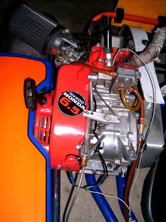 From this lever I use a pushrod made from a bicycle wheel spoke to
actuate the carb throttle lever. I have a bend in this pushrod so that when the
carb lever reaches its stop the pushrod will bend, or buckle, and not put
excessive force on the carb lever. The pushrod is such that it returns to its
normal shape when the accelerator is released. The relay lever also reverses the
direction of travel so that the accererator cable can extend forward directly
towards the pedal. In my layout I mount the accererator cable to one of the
front fuel tank ears. Another method of achiving over-travel safety, is to
insert a tension spring between the cable end and the lever or pedal. For a
throttle cable, I use a bicycle long shifter cable (the light variety) which I
buy without a sheath. For a cable sheath I use 3/16" nylon tubing with
compression fittings for end attachments. The cable is quite loose in the tubing
and doesn't bind. To mount the sheath to the motor I drill and tap the front of
the fuel tank mount ear 1/8" NPT for the compression fitting.
From this lever I use a pushrod made from a bicycle wheel spoke to
actuate the carb throttle lever. I have a bend in this pushrod so that when the
carb lever reaches its stop the pushrod will bend, or buckle, and not put
excessive force on the carb lever. The pushrod is such that it returns to its
normal shape when the accelerator is released. The relay lever also reverses the
direction of travel so that the accererator cable can extend forward directly
towards the pedal. In my layout I mount the accererator cable to one of the
front fuel tank ears. Another method of achiving over-travel safety, is to
insert a tension spring between the cable end and the lever or pedal. For a
throttle cable, I use a bicycle long shifter cable (the light variety) which I
buy without a sheath. For a cable sheath I use 3/16" nylon tubing with
compression fittings for end attachments. The cable is quite loose in the tubing
and doesn't bind. To mount the sheath to the motor I drill and tap the front of
the fuel tank mount ear 1/8" NPT for the compression fitting.
Install Header and Muffler. Firstly
you can build your own header, as I do, if you have a MIG welder. I have a local
fab shop plasma cut the flange plate and pre bend the tube. I use 1" OD x 0.040"
wall 4130 (chrome-molly) aircraft tube. This tube is a bit tricky to bend
without buckling, but if you use a large radius and limit the bend angle it will
turn out fine. Do not try bending it without a good tube bender. To have flanges
cut you can download the following CAD and Acrobat files. The fab shop can use
the CAD file to program their cutting machine.
FLANGE CAD FILE
(.dxf)
FLANGE ACROBAT
FILE (.pdf)
It is a good idea to weld a small stopper to the tube to
locate the muffler, as the tube must insert at least 1" into the muffler to be
legal. The stopper will give you an easy inspection reference and prevent the
header from going too far into the muffler and thus hurting performance.
Install air filter and filter adapter.
Rules affecting air filters and air filter adapters have changed
periodically. Make sure you understand the current rules and use components that
meet them. There may be some parts, new or used, out there that do not conform
to the current rules and should be avoided.
Install clutch. My comments here apply
to the "Max Torque, Draggin' Skin" type of clutch, but may also apply to other
brands as well. The clutch may be installed with the drive sprocket inboard or
outboard, whichever way works best for your situation. The clutch is retained
with a 5/16 UNF bolt and flatwasher in the end of the crankshaft. When installed
the clutch will have some "end play" on the crankshaft and can float in and out.
This is OK. I tried clamping the clutch tight with no end play, my fist time,
and only damaged the clutch drive hub. Your clutch should be serviced after each
race. I clean and de-glaze the drum and shoes, and clean and re-oil the bushing
with two drops of oil. Do not over oil the bushing as it will bleed onto the
shoes and prevent lockup.
| Parts
required to build and install a Honda GX200 engine. |
|
|
|
| Part number |
Quantity |
Description |
Sources |
| GX200QH |
1 |
Honda 6.5 HP engine |
|
| 99101-ZF50780 |
1 |
#78 main jet, used during
break in period. |
|
| 99101-ZF50750 |
1 |
#75 main jet. |
|
| 16166-ZE1-005 |
1 |
GX140 emulsion tube (nozzle) |
|
| 12391-ZE1-000 |
0 |
Valve cover gasket |
|
| 12251-ZL0-003 |
0 |
Head Gasket (shim
style) |
|
| 11381-ZB2-800 |
1 |
Crankcase side cover
gasket |
|
| 18381-ZH8-800 |
0 |
Exhaust header
gasket |
|
| 13331-357-000 |
0 |
Flywheel key (file to advance
ignition timing). |
|
| 13013-ZL0-001 |
1 |
Piston ring set, 0.25 mm
oversize (grind to 0.006" gap) |
|
| 14751-883-000 |
2 |
Valve spring, G200 |
|
| BPR6ES |
1 |
NKG spark plug. |
Auto Supply |
| |
1 |
Fuel pump from a Honda
GC160 |
|
|
1 |
#6-32 allen head set screw, 3/8" long |
Industrial Supply |
| 325-4A or 125-4A |
1 |
1/8 npt to 1/4" barb fitting
(pump pulse) |
Industrial
Supply |
| |
1 |
RLV-B91-1" muffler |
Kart Shop |
| |
1 |
Honda 1" x 12" header
pipe. |
Kart Shop |
| |
1 |
1/8 x 3/4 steel flatbar 16"
long for muffler brace. (should be supplied with header) |
|
| |
1 |
Stainless hose clamp 1"
(muffler to header) |
|
| |
1 |
Stainless hose clamp 2-1/2"
(brace bar to muffler) |
|
| |
10 |
Header wrap tape 1"
wide. |
Auto Supply |
| |
1 |
Air filter adapter |
|
| |
1 |
Air
filter |
Kart Shop |
| |
1 |
Engine mounted chain
guard. |
Kart Shop |
| |
1 |
Dragon Skin Clutch Kit wit
13, 14, & 15 tooth drivers and black shoes |
Kart Shop |
| |
1 |
Dragon Skin 10 gram weight
kit. |
Kart Shop |
| |
1 |
62 tooth #35 split rear
sprocket.(plus other sizes as required) |
Kart Shop |
| |
1 |
#35 chain, 36" long |
Industrial
Supply |
| |
1 |
"Rust Check" spray Chain
lube) |
Canadian Tire |
| |
1 |
3/16" fuel hose (yellow that
stays soft). |
|
| |
5 |
1/4" fuel hose (yellow that
stays soft). |
|
| |
1 |
Fuel primer bulb,
1/4" |
Canadian Tire |
| |
0 |
4 cycle racing oil (14oz per
fill) |
Kart Shop |
| |
0 |
or - Amsoil 0-30w synthetic
(14oz per fill) |
|
| |
1 |
5-30w motor oil for break in
only then switch to synthetic |
Canadian Tire |
| |
1 |
Throttle cable (lightest
bicycle shifter cable) |
Bicycle store |
| |
1 |
Throttle cable sheath, loose
fit.(bicicle brake cable sheath or 3/16" nylon tubing) |
Bicycle store or Industrial
Supply |
|
2 |
Cable sheath end compression fitting, 68-3A (1/8" NPT to 3/16
tube) |
Industrial Supply |
| |
1 |
Throttle cable end
spud |
|
| |
1 |
Motor mount, 4
cycle |
Kart Shop |
|
|
|
|
top of
page
Need a Degree Wheel?
Make your own. Just download my degree
wheel drawing, print it off on as large a sheet of paper as you can, cut it
out and glue it to a piece of aluminum or masonite. Drill the center for your
5/16 clutch bolt, and your done. Make up a pointer that bolts to the fuel tank
ear on the block and file or grind a chisel point on it. The larger your degree
wheel is the easier it is to get accurate readings.
Download my "Engine build report" sheet in Microsoft
Office format or Adobe
Acrobat format. Or the Cam Profile
Spreadsheet.
Here's a handy chassis setup and timing
record sheet that we use.
Some other links:
Do it yourself karting -
Jamie Webb's self help site has lots of good tech info.
top of
page